
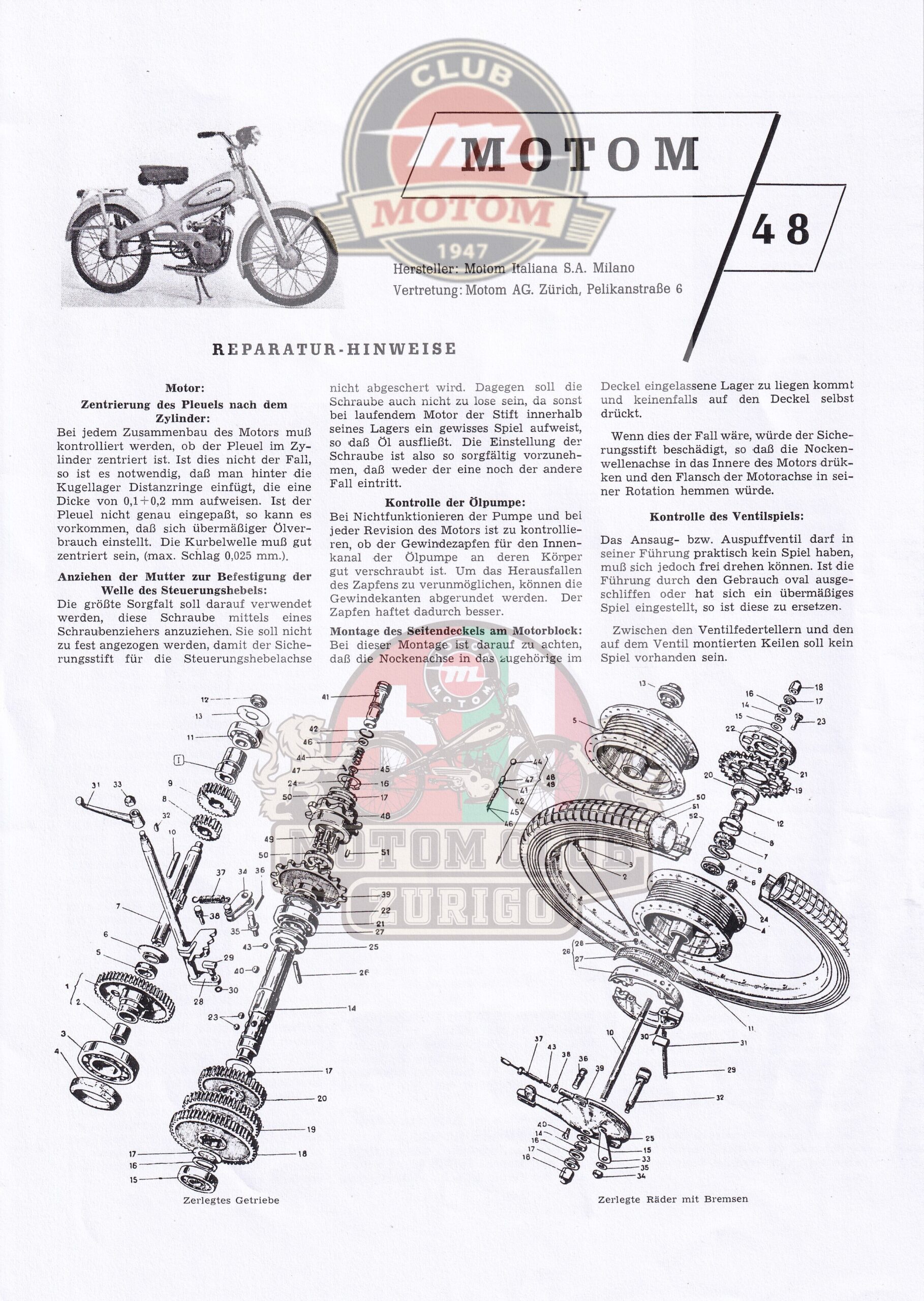
This is the Motom 48 repair manual, translated into Italian from the original German "Reparatur-Hinweise".
A previously unpublished and likely unique Motom 48 repair manual published for the Swiss market.
Manufacturer: Motom Italiana S.A., Milan Distributor: Motom AG, Zurich, Pelikanstraße 6
Translation from the original German "Reparatur-Hinweise".
Note for German-speaking readers: We recommend referring directly to the original German manual. This translation was done from Italian and may contain inaccuracies in terminology.
Document courtesy of Massimo Prata of the Motom Club Zurich

ENGINE
Piston Alignment in the Cylinder: Every time the engine is reassembled, check that the piston is centered in the cylinder. If it is not, insert spacer rings with a thickness of 0.1 to 0.2 mm behind the ball bearing. If the piston is not properly centered, excessive oil consumption may occur. The crankshaft must be well centered (max. runout 0.025 mm).
Tightening the gearshift lever shaft retaining nut: Extreme care must be taken when tightening this screw with a screwdriver. It must not be overtightened, so as not to damage the safety pin on the gearshift lever shaft. On the other hand, it must not be too loose, as otherwise, with the engine running, the pin would have play in its seat. Tightening must therefore be performed precisely to prevent either of these problems from occurring.
Checking the oil pump: If the pump fails to operate, and during every engine overhaul, verify that the threaded stud in the pump’s internal channel is properly screwed into the pump housing. To prevent the pin from loosening, chamfer the threaded edges: this improves the seal.
Installing the side cover on the engine block: During this procedure, ensure that the camshaft pin is seated in the designated bearing located in the cover, and under no circumstances resting on the cover itself. If this were to occur, the safety pin would be damaged: the camshaft would press inward toward the engine, and the drive shaft flange would prevent its rotation.
Checking valve clearance: The intake and exhaust valves should have virtually no clearance, but they must be able to rotate freely. If the seat has become oval-shaped due to wear, or if excessive clearance has developed, this must be eliminated. There must be no play between the valve spring seats and the half-cones mounted on the stem.
CHANGE
Installing the retaining ball on the drive shaft: When installing the drive shaft, do not forget the retaining ball and its spring (parts 41–44), which are housed inside the central pin (14). It is the selector that, by sliding inside the pin, pushes the balls outward, causing them to engage with the gear wheels. If the retaining ball is missing, the mechanism cannot hold the selector in position, and the gears will not engage properly.
Installing the oil seals: When installing the oil seals on the drive shaft after mounting the gearbox gears, make sure that the lip of the oil seal faces toward the inside of the engine. You must also ensure that the teeth of the first engagement gear do not rub against the inner surface of the oil seals. Finally, ensure that the gears are properly lubricated. Even the slightest misalignment can cause the clutch to overheat.
CLUTCH
Clutch adjustment: If the clutch operated by the handlebar lever does not disengage sufficiently, adjust it using the adjustment screw. However, if the adjustment screw has already been fully tightened during previous adjustments and further adjustment is not possible, the new adjustment is made by moving the clutch cable to a different hole in the mounting plates.
Clutch bushing seizure: It may happen that the engine continues to turn even when the clutch lever is engaged. The problem is caused by the sprocket on the drive shaft being seized. To fix this, remove the sprocket and the bronze bushing and grind them down by a few hundredths of a millimeter, smoothing out any irregularities on the drive shaft if necessary.
Adjusting the selector fork rod: If you are unable to engage a specific gear while the engine is running, check that the sprocket mounted on the fork rod is precisely centered within its housing on the drive shaft. To do this, open the engine casing and remove the drive shaft sprockets along with their respective selector cams. Ensure that a wedge is inserted beneath the drive chain sprocket to press the crankshaft bearing firmly into its seat, eliminating any axial play. Then, by operating the external gearshift lever, engage the three gears one after the other. The exact position of the gear ring relative to the housings can be checked using a small mirror inserted into the casing opening. If the sprocket is not properly centered, bend the drive shaft plate horizontally until it fits into all three positions. Be careful that the bending does not detach the weld point of the plate from the fork arm.

TECHNICAL SPECIFICATIONS
Engine
| Entry | Value |
|---|---|
| Type | 4-stroke |
| Cylinders | 1 |
| Bore | 39 mm |
| Running | 40 mm |
| Displacement | 48 cc |
| Maximum power at 4,500 rpm | 1.7 hp |
| Compression ratio | 7:1 |
| Cooling | Air-cooled |
Broadcast
| Entry | Value |
|---|---|
| Gear ratio | Straight-toothed cylindrical gears |
| Speeds | 2,63:1 |
| 2nd gear | 1,69:1 |
| 3rd gear | 1:1 |
| Clutch | Single-disc dry clutch |
General Information
| Entry | Value |
|---|---|
| Electrical system | 6V, 15W |
| Shock absorbers | In the rear wheel hub |
| Hand brake | 2 oversized cables |
| Tire size | 2,00×18 |
| Step | 1.13 m |
| Width | 0.70 m |
| Height | 0.95 m |
| Dry weight | 41.5 kg |
| Fuel consumption | 1.3 L/100 km |
| Maximum speed | 40 mph |
Workshop data — Piston
| Entry | Value |
|---|---|
| Original size | 39 mm |
| Oversized | 39.4 and 39.8 mm |
| Piston-cylinder clearance | 0.05 mm |
Plug
| Entry | Value |
|---|---|
| Diameter | 11 mm |
| Length | 32 mm |
| Axial play | 0.015 mm |
Segments
| Entry | Compression | Oil scraper |
|---|---|---|
| Number | 2 | 1 |
| Width | 2 mm | 2.5 mm |
| Service game | 0.2 mm | 0.2 mm |
| Side play | 0.02 mm | 0.02 mm |
Crankshaft
| Entry | Value |
|---|---|
| 1st main bearing journal Ø | 15 mm |
| Length | 13 mm |
| 2nd main bearing journal Ø | 15 mm |
| Length | 10 mm |
| Crankpin Ø | 20 mm |
| Length | 9 mm |
| Axial play | 0.1–0.2 mm |
Camshaft
| Entry | Value |
|---|---|
| Bearing seat diameter | 10 mm |
| Building game | 0.03 mm |
| Total length | 56 mm |
| Camshaft profile angle | 45° |
Valves
| Entry | Value |
|---|---|
| Head diameter | 15 mm |
| Shaft diameter | 5 mm |
| Total length | 56 mm |
| Office Corner | 45° |
| Guide Rod Game | 0.025 mm |
| Cold valve play | 0.15 mm |
Timing
| Entry | Value |
|---|---|
| Suction opens | 16 days before PMS |
| Suction shuts off | 44th after the PMI |
| Drain opens | 44th before the PMI |
| Drain plug | 16 days after PMS |
Power On
| Entry | Value |
|---|---|
| System | Flywheel magnet generator |
| Voltage | 6V, 15W |
| Champion Spark Plug | 10 hours to go |
| Bosch Spark Plug | W 175 T1 |
| AC Candle | 45-L |
| Auto-Lite Spark Plug | AL-5 |
| Candela Marelli | CW 175 A |
| Electrode spacing | 0.5 mm |
| Maximum advance | 23° = 22 mm at the flywheel |
| Pin spacing | 0.5 mm |
| Capacitor capacity | 0.12–0.15 μF |
Carburetor
| Entry | Value |
|---|---|
| Type | Weber 14 MFM |
| Venturi diameter | 9 mm |
| Main jet | No. 60 |
| Idle jet | No. 40 |
| Floating weight | 5 g |
Brakes
| Entry | Value |
|---|---|
| Front type | Drum-type, internal brake shoes |
| Front drum diameter | 107 mm |
| Rear type | Drum-type, internal brake shoes |
| Rear drum diameter | 107 mm |
Capacity
| Entry | Value |
|---|---|
| Fuel tank | 3.5 L |
| Reserve | 0.3 L |
| Motor oil | 0.4 L |
| Winter oil | SAE 30 |
| Summer Oil | SAE 40 |
For more information on this article, please see:
All Guides Guides
Reboring the Motom Crankshaft — What You Need to Know
Which Spark Plug to Use on a Motom — The Definitive Guide
What Oil to Use in Your Motom — The Definitive Guide
If you found this article useful and would like to help keep Motom Club alive, you can support the project with a small contribution.
SUPPORT MOTOM CLUBAll content on this site is protected by copyright. Reproduction, even partial, is prohibited without written permission.